
Key Takeaway: Properly resetting, operating, and maintaining a cardboard baler requires a clear understanding of its hydraulic and electrical systems, adherence to safety protocols, and systematic troubleshooting. Regular inspections and preventive maintenance will drastically reduce downtime and extend equipment life.
1. Introduction
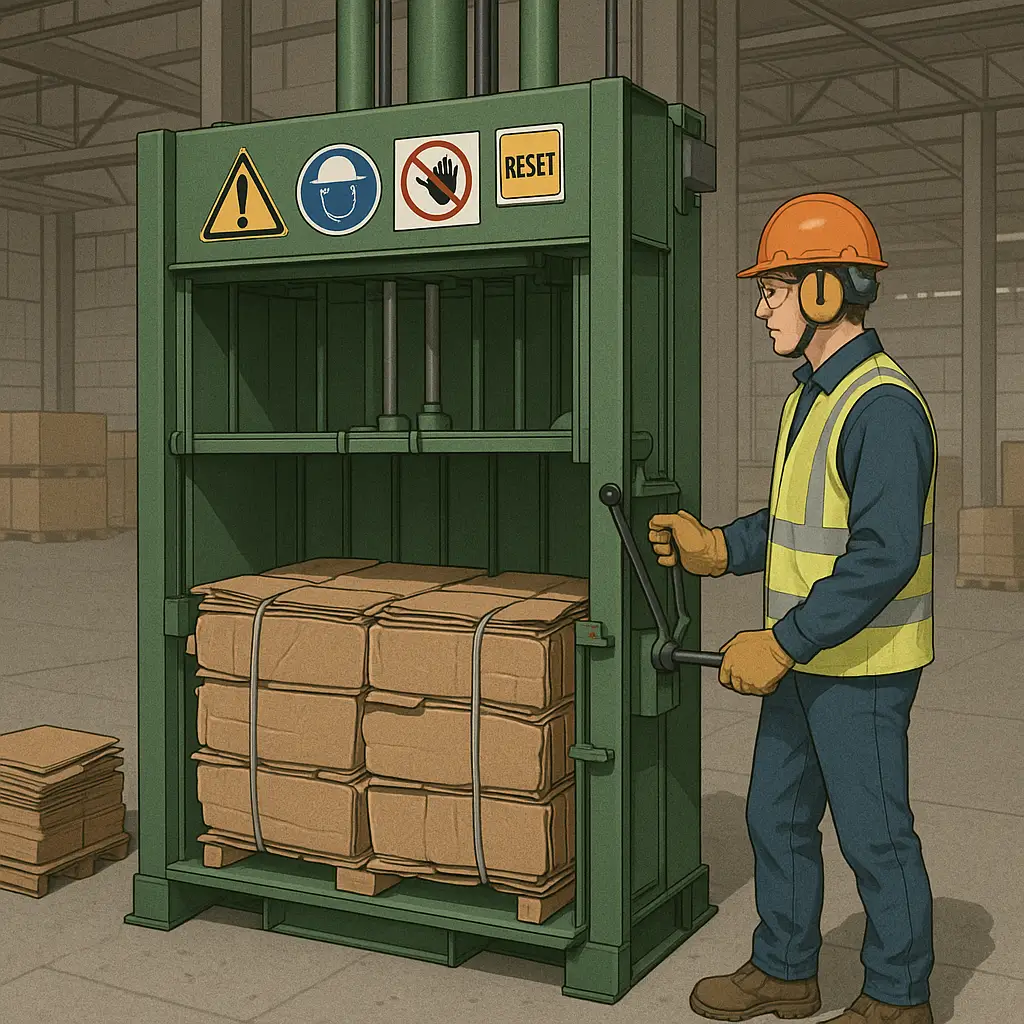
Cardboard balers are essential equipment in recycling and waste-management operations. They compress cardboard into dense bales for efficient handling and transport. Despite their robust design, balers occasionally require resetting, alternative operation methods (e.g., when an up/down switch is missing), and mechanical or electrical repairs. This guide provides step-by-step instructions covering:
- Safety precautions
- How to perform a full reset
- Methods to operate a baler without a conventional up/down switch
- Common faults and repair procedures
2. Essential Safety Precautions
Before interacting with any machinery, safety must be the top priority. Failure to comply with safety standards can result in serious injury or damage.
- Lockout/Tagout (LOTO):
- Isolate energy sources (electrical, hydraulic, pneumatic) by disconnecting power and bleeding residual pressure.
- Attach lockout devices and tags to inform others that the machine is offline.
- Personal Protective Equipment (PPE):
- Hard hat, safety goggles, and steel-toed boots.
- Gloves rated for hydraulic oil and grease resistance.
- Hearing protection if noise exceeds 85 dB.
- Operational Area Clearance:
- Keep all non‐essential personnel at a safe distance (minimum 2 m).
- Post warning signs and barriers around the baler.
- Inspection Before Work:
- Check for hydraulic leaks, loose fasteners, and frayed electrical wires.
- Ensure emergency stop (E-stop) is functional.
3. Resetting a Cardboard Baler
A reset procedure is often necessary after an overload, power failure, or E-stop activation. The exact method can vary by manufacturer, but the following universal procedure applies to most balers.
3.1 Identify the Cause of Shutdown
- Thermal overload: Motor overheats and trips internal breaker.
- Hydraulic pressure spike: Relief valve activates.
- E-stop or safety interlock: Door or gate open.
3.2 Electrical Reset Sequence
- Confirm Power Is Off:
- Verify main disconnect switch is in OFF position.
- Clear Fault Codes (if applicable):
- On balers with a PLC or digital controller, navigate the menu to “Fault Diagnostics” and clear all codes.
- Reset Thermal Overload:
- Locate the thermal overload reset button on the motor starter. Press and hold for 2 seconds.
- Restore Power:
- Move the main disconnect to ON.
- Verify indicator lights on control panel.
3.3 Hydraulic Reset Sequence
- Cycle the Valve Manually:
- On systems equipped with manual override levers, shift the directional control valve to neutral, then to either extend or retract, and back to neutral. This bleeds trapped air.
- Bleed Air from Cylinders:
- Loosen bleed fittings on top of hydraulic cylinders and pump until a steady stream of oil (no air bubbles) emerges, then retighten.
- Check Relief Valve Setting:
- Using a calibrated gauge, ensure the relief valve pressure matches the manufacturer’s specification (typically 2,500–3,000 psi).
- Test Cycle:
- Run a dry cycle (no load) to confirm smooth, full-stroke operation.
4. Operating a Cardboard Baler Without an Up/Down Switch
Some older or custom balers may lack a dedicated up/down rocker or push-button switch. In these cases, alternative methods are used.
4.1 Manual Valve Lever Operation
Many balers equipped with hydraulic systems feature an external manual control lever for directional valves:
- Locate the Manual Override Lever: Usually adjacent to the valve bank or integrated into the main hydraulic manifold.
- Neutral Position: Center the lever to disconnect flow and hold the ram stationary.
- Extend (Downstroke): Push the lever fully forward to direct oil flow to the rod end of the cylinder.
- Retract (Upstroke): Pull the lever fully back to send oil to the cap end of the cylinder.
- Return to Neutral: Always center the lever after reaching the desired position.
4.2 Push-Button Control Retrofit
If manual levers are unavailable or inconvenient:
- Install a Two-Button Pendant:
- Powered by the baler’s control voltage (usually 24 V DC).
- Wire one button to the open solenoid coil and one to the close solenoid coil on the directional valve.
- Safety Interlock Integration:
- Include seal-in contacts so the operator must hold the button continuously for motion to occur.
- Wire the E-stop circuit in series to both buttons.
4.3 PLC or Relay Logic Control
For balers with a programmable logic controller (PLC):
- Identify I/O Modules: Locate the input terminals for the missing up/down switch signals.
- Assign New Inputs: Use spare inputs tied to momentary push-button stations.
- Program Ladder Logic:
- Rung 1: When ‘Down’ button input is true, energize ‘Down’ solenoid Y1.
- Rung 2: When ‘Up’ button input is true, energize ‘Up’ solenoid Y2.
- Interlocks: Prevent both solenoids from energizing simultaneously.
- Test Functionality: Verify that each button actuates the correct valve function and that interlocks prevent conflicts.
5. Common Baler Issues and Repair Procedures
This section covers troubleshooting steps for frequent mechanical and electrical faults.
5.1 Hydraulic System Problems
5.1.1 Slow Ram Movement
- Causes: Low hydraulic fluid level, contaminant-laden fluid, clogged filters, worn pump.
- Procedure:
- Fluid Level Check: Ensure reservoir is at “Full” mark. Top off with ISO VG 46 hydraulic oil.
- Filter Replacement: Replace suction and return-line filters if differential pressure > 20 psi.
- Fluid Analysis: Send a sample for particle count and water content.
- Pump Inspection: Listen for unusual noises; if cavitation is present, replace or rebuild pump.
5.1.2 Hydraulic Leaks
- Causes: Damaged hose, failed seal, loose fittings.
- Procedure:
- Visual Inspection: Identify leak location.
- Pressure Test: Run at 1,500 psi and inspect connections with leak-detect spray.
- Component Replacement: Use OEM hoses and seals rated for ≥ 3,000 psi.
- Torque Fittings: Tighten to manufacturer’s specification (e.g., 30 ft-lb for 3/8″ NPT).
5.2 Electrical and Control Faults
5.2.1 Baler Won’t Start
- Causes: Blown fuse, tripped breaker, faulty start/run capacitors, defective motor starter.
- Procedure:
- Breaker and Fuse Check: Reset breaker; replace fuse if blown.
- Voltage Verification: Confirm 460 V (or 230 V) three-phase at motor terminals.
- Capacitor Test: Use an LCR meter to check capacitance within ± 5% of rating.
- Contactor Test: Energize coil; if contacts do not close, replace starter.
5.2.2 Intermittent Control Panel Lights
- Causes: Loose wiring, defective LED module, voltage fluctuation.
- Procedure:
- Pull Panel: Inspect terminal block connections for tightness.
- Measure Supply Voltage: Ensure stable 24 V DC supply.
- LED Module Replacement: Swap indicator board; verify restoration.
5.3 Mechanical Wear and Maintenance
5.3.1 Worn Cylinder Rods
- Symptoms: Scoring, pitting, or bending of rods; oil weeping.
- Procedure:
- Rod Inspection: Disassemble cylinder; polish minor scratches with 600-grit sandpaper.
- Seal Replacement: Install polyurethane rod seals and wipers.
- Rod Straightness: Use a dial indicator; replace if runout > 0.005″ TIR.
5.3.2 Frame or Door Misalignment
- Symptoms: Door latches won’t engage; bales jam in chamber.
- Procedure:
- Check Hinge Pins: Lubricate or replace worn pins.
- Shimming: Loosen mounting bolts; insert metal shims to realign frame.
- Torque Bolts: Re-tighten to spec (e.g., 50 ft-lb for M16 bolts).
6. Preventive Maintenance Best Practices
A robust preventive maintenance (PM) program minimizes unplanned downtime and repairs.
- Daily Checks:
- Visual inspection for leaks and loose fittings.
- Confirm proper bale ejection and platen travel.
- Weekly Tasks:
- Top off hydraulic fluid and check oil contamination.
- Test E-stop and all safety interlocks.
- Monthly Maintenance:
- Replace return-line filters.
- Inspect hoses for cracking or wear.
- Quarterly Preventive Overhaul:
- Flush hydraulic reservoir and replace all filters.
- Perform vibration analysis on motor and pump coupling.
- Exercise all valves and solenoids.
- Annual Service:
- Complete system teardown and rebuild critical components.
- Calibrate relief valves, pressure switches, and sensors.
7. Conclusion
Resetting, operating, and repairing a cardboard baler involves a systematic approach to safety, electrical and hydraulic systems, and mechanical integrity. By following the detailed reset procedures, employing alternative operation methods in the absence of standard controls, and executing targeted repairs for common faults, operators can ensure reliable and safe baler performance. Implementing a structured preventive maintenance program will further extend the service life of the baler and optimize uptime.
Leave a Reply